Introduction
This is an ongoing project to develop very inexpensive hardware and software to help amateur radio folks with D-Star.It started with goal of developing a really, really inexpensive GMSK DV Adapter to use with the Raspberryt Pi and the Arduino boards. There are already many different DV Adapters available, but all of them are in the $100+ range. When looking at the basic Bill of Materials (BOM) it looked like the cost could be brought down dramatically. Next it was the development of new GMSK hardware for the Pi to work around the bugs in the Broadcom drivers. And finally it was the development of a board to allow the inexpensive radio module from Analog Devices to be used for a Pi hotspot.
All these web pages detail the design and building of all these boards. All the designs are released as open source. All the hardware CAD files, the firmware and software are made available.
|
|
|

|
|
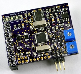
RasPi DV AVR
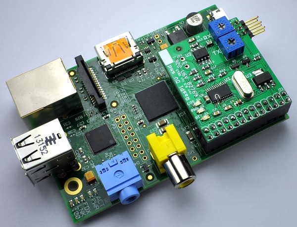
This board is the more advanced version of the RasPi DV board. In includes an onboard ATMega328 chip to take care of all the interrupts and bit managing from the CMX589 chip. Go to the RasPi DV AVR page for more information.
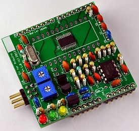
DV for Arduino
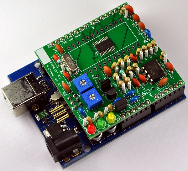
This board is a GMSK adapter designed as an Arduino shield and the software is designed to make the board appear to be a DV-RPTR. This would allow for the board to be supported in existing D-Star programs with very minor software changes. It has a Bill of Materials cost of about $8. Go to the DV for Arduino page for more information.
RasPi ADF7021
This board is the adapter board to go between the Raspberry Pi and the ADF7021 evaluation radio board. Go to the RasPi ADF7021 page for more information.
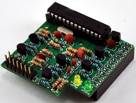
RasPi DV
This board is a GMSK adapter designed as a Raspberry Pi daughter board to plug into the GPIO conector. It has a Bill of Materials cost of about $8. Go to the RasPi DV page for more information.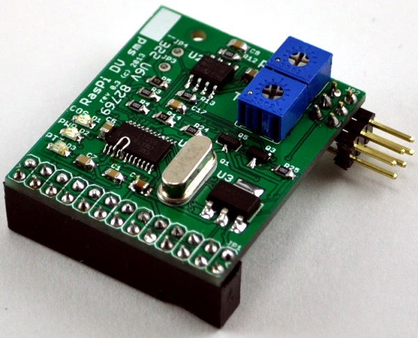
It is a great little design except for one big problem - lost interrupts on the Pi. The GMSK board generates two clock signals that are sent to the Pi, one for transmit data and one for receive data. The software on the Pi receives an interrupt for every rising edge of the clocks. The problem has to do with the Broadcom device drivers that handle the GPIO pins. There is a well known bug in the driver that only allows one interrupt to be in progress at the same time. This means that if the transmit or receive clocks are aligned, the software will not get one of the two interrupts. In practice this means that about 1 out of every 50 clock edges is lost. The D-Star error correction built into the AMBE codec cannot handle lost bits very well and a 2% loss rate is much too high for it to handle.
We've been in contact with Broadcom asking for help to fix the problem. Unfortunately they declined our request. We've also seen posts describing the same problem in the Pi forums, but so far none of the suggested fixes solves the problem.
Narrowing down the problem took a lot of time and effort. A rather large kernel driver had to be written and debugged. We got the kernel driver working well enough for a very specific set of conditions. If the board is used for only recording, or only playback, AND all the data is written to/read from a single kernel buffer, AND there is NO user mode interaction with the driver, THEN it will work pretty well. It isn't a set of conditions that would allow anyone to create a hotspot. The source code to the kernel driver is available via the downloads page.
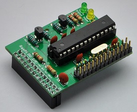
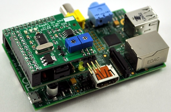
RasPi DV I/F
This board is the adapter board to go between the Raspberry Pi and the RasPi DV board and adds the functionality of the Arduino to control the CMX589 chip. Go to the RasPi DV page for more information.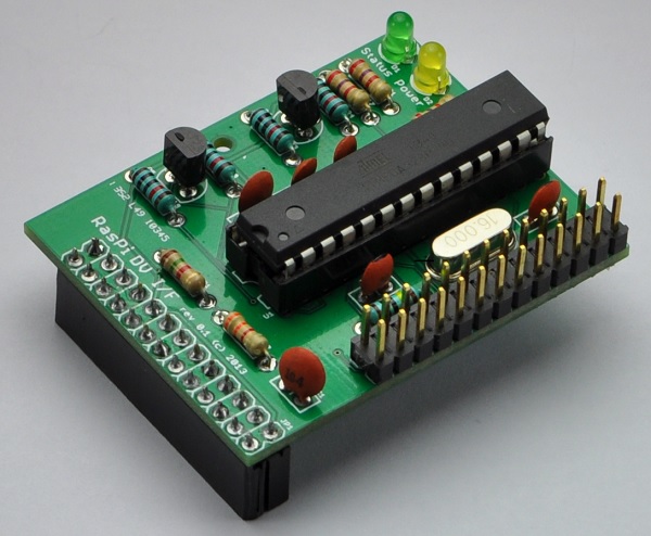
Images of these boards plugged into the Raspberry Pi and Arduino
The image below is the RasPi DV AVR board plugged into a Raspberry Pi.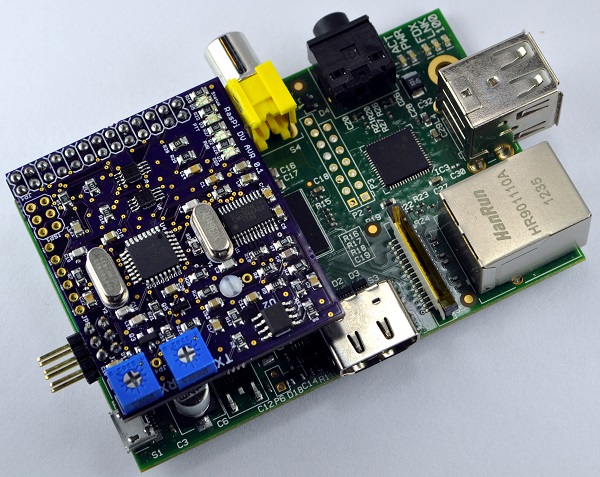
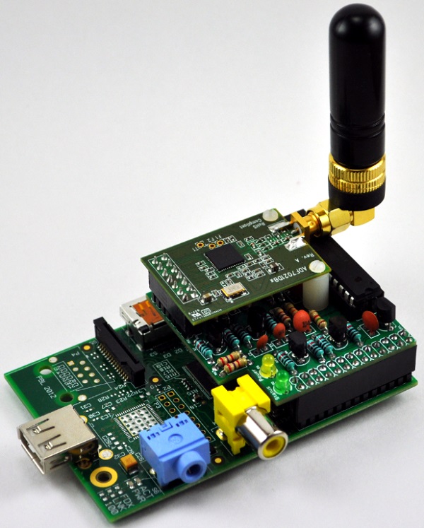
The image below is the ADF7021 radio module plugged into the RasPi ADF7021 board plugged into a Raspberry Pi.
The image below is the RasPi DV GMSK board plugged into a Raspberry Pi.
The image below is the RasPi DV GMSK board plugged into RasPi DV I/F adapter board plugged into a Raspberry Pi.
The image below is the DV for Arduino adapter plugged into the Arduino UNO board.
Raspberry Pi
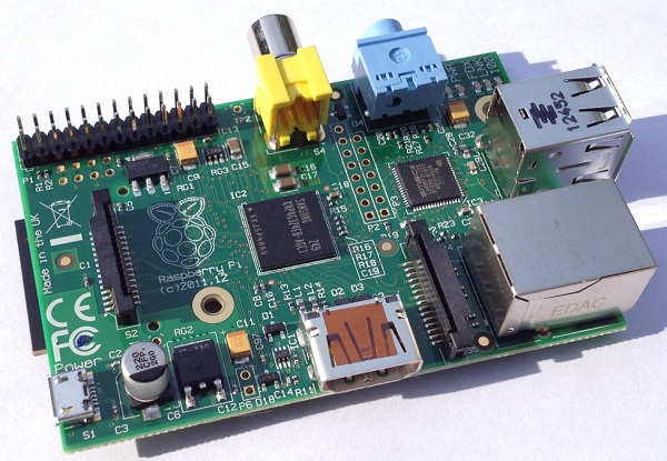
What is a Raspberry Pi? To borrow from the: Raspberry Pi wiki page:"The Raspberry Pi is a credit-card-sized single-board computer developed in the UK by the Raspberry Pi Foundation with the intention of promoting the teaching of basic computer science in schools." For more information, visit the Raspberry Pi Foundation website
The image below is a Raspberry Pi ver 2 board used in the development the Pi software and driver.
Arduino
What is an Arduino? To borrow from the: Arduino Wiki page:"Arduino is a single-board microcontroller designed to make the process of using electronics in multidisciplinary projects more accessible. The hardware consists of a simple open source hardware board designed around an 8-bit Atmel AVR microcontroller, though a new model has been designed around a 32-bit Atmel ARM. The software consists of a standard programming language compiler and a boot loader that executes on the microcontroller." For more information, visit the Arduino website
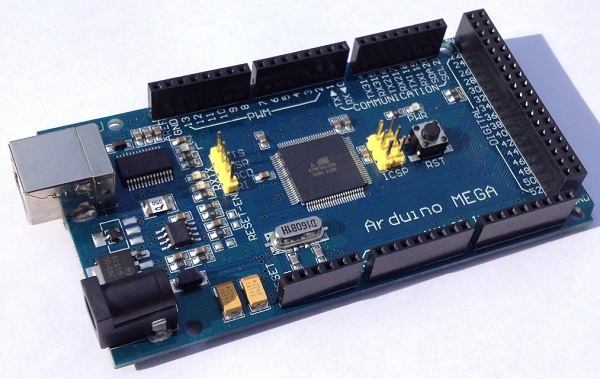
The image below is an Arduino Mega1280 used in the development the Arduino firmware.
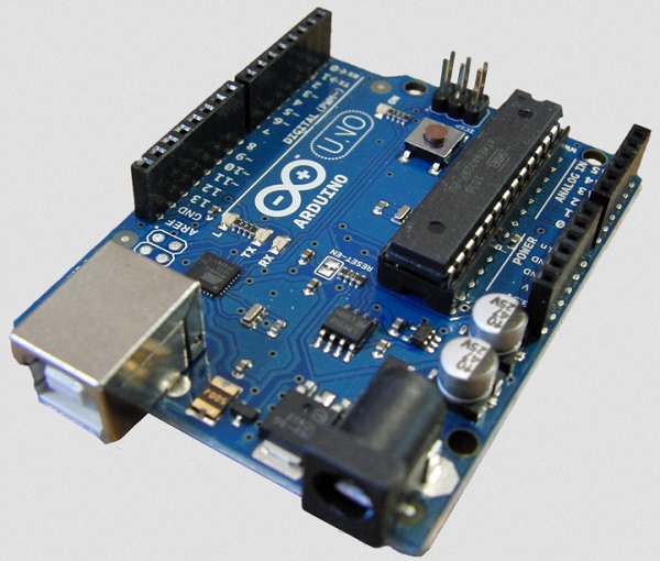
The image below is an Arduino UNO used in the development the Arduino firmware.
Block diagram
The GMSK board consists of a small number of parts thanks to the number of functions that are packed into the CMX589 chip. There is a control interface with the CPU and an analog input/output. The analog circuity includes an op-amp to allow signal level adjustment as well as bandpass filtering.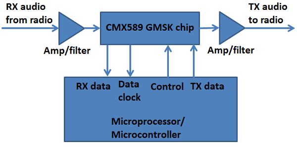
Raspberry Pi Mechanical/Electical
The PCB were designed with a number of factors in mind, including:- attempting to fit inside most Raspberry Pi cases
- selecting pins on GPIO connector such that the serial port and I2C interfaces are left untouched allowing for other daughter boards or future enhancements
- having the least amount possible of overlap of the processor allowing for a head sink to be installed and allow plenty of airflow
- a mounting hole for additional strength when using a stand-off with rev. B boards
- a small, commonly available connector to the radio cable, allowing for easy modification of existing cases
- using the smallest components possible and still allow DIY assembly of the board
- having the smallest possible board size to keep the cost low
- operating as much as possible at 3.3V to keep current low enough to be powered over the GPIO connector
Arduino Mechanical/Electical design
The PCB was designed with a number of factors in mind, including:- a small, commonly available connector to the radio cable
- using all through-hole components to allow easy DIY assembly of the board
- having the smallest possible board size to keep the cost low
- operating entirely at 5V and requiring low enough current to be powered over the Arduino GPIO pins
First prototype
The first step in the project was to build a prototype of the core parts of the hardware on a solderless breadboard. It was then hooked up to an Arduino board from Seeed Studio.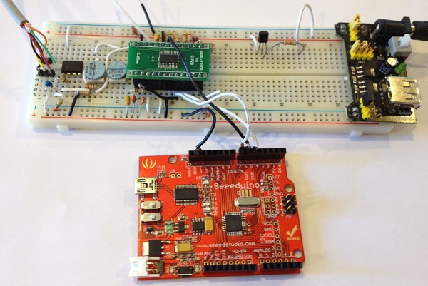
All text and images on ki6zum.com are copyright (c) 2010-2014 and may not be reproduced in any form without written permission.