Raspberry Pi DV AVR
The design of the Raspberry Pi DV AVR board is a GMSK board combined with the basic circuitry of an Arduino. This allows the ATMega328 chip to handle all the interrupts and bit managing so that the software on the Pi can think it is communicating with a GMSK board connected via virtual serial port over USB. The added devices and larger PCB mean a slightly higher BOM cost than the original RasPi DV board.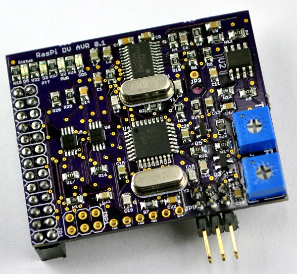
Schematic
The schematic diagram and PCB layout was done using Eagle CAD. They offer a limited free version of the software available for Windows, Mac and Linux. The PDF of the schematic diagram can be found on the GMSK downloads page.Mode jumpers
The board hardware has been designed to operate in any one of three modes:- GPIO serial mode - this is the typical mode which has all communication with the Pi going over the serial port on the GPIO connector. J3 and J7 connected, J4 not connected
- GPIO I2C mode - this is an alternate mode that uses the shared I2C bus instead of the non-shareable serial port. J4 connected, J3 and J7 not connected
- FTDI interface mode - This mode uses the standard FTDI adapter to give a USB connection to the PC. J3, J4 and J7 not connected
ISP header
This is a 6 pin (3x2) male header used to program the ATMega328 chip. It is the standard ATMEL AVR In-Sysmtem Programming (ISP) connector. The ATMega328 can be programmed with various hardware such as the USBASP or AVRISP boards.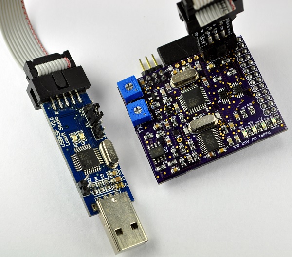
FTDI header
This is a 6 pin (6x1) female connector which allows the use of a USB connection to the computer via a standard FTDI breakout board such as the Sparkfun FTDI Basic Breakout.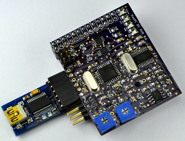
Status LEDs
There are four status LEDs on the board:- Status - This LED is configured to mimic the built-in LED on most every Arduino board. The firmware can make use of it to show data transfer status.
- PTT - This red LED is connected to the transistor that controls the PTT signal being sent to the radio. It will turn on every time the firmware activates the PTT.
- PWR - This yellow LED will be on as long as there is 5V supplied to the board from the Pi.
- COS - This green LED is used by the firmware to signal when a receive audio stream has been detected.
Test points
There are two test points on the board. The first one is JP3 which is the receive analog feedback signal, and the second one is JP4 which is the transmit analog signal. These two signals can be used to help adjust the variable resistors. See the tuning instructions here.Software
The ATMega328 chip on the board uses the exact same firmware as the DV for Arduino board. The firmware is compiled for the Arduino UNO and uses the standard UNO Optiboot bootloader. The host side software on the Raspberry Pi is The G4KLX DStar Repeater application using DV-RPTR V1 modem mode. The links to the firmware and software test files can be found on the downloads page.Bill of Materials
For the most part, all the parts are available from either Mouser and/or Tayda Electronics. The PCBs can come from a service such as OSH Park or Seeed Studio.The prices below are based on purchasing enough parts in bulk to make kits for at least 10 boards. Buying the parts for just a single board would cost quite a few dollars more. The pricing for the resistors and capacitors is based on buying at least multiples of 100 at a time. The pricing for parts at Tayda assumes using 15% discount they regularly post on their Facebook page.| Category | Description | Qty | Designators | Price | Ext | Vendor link |
|---|---|---|---|---|---|---|
| Semiconductors | ||||||
| CMX589AE2 | 1 | U1 | $3.700 | $3.700 | eBay | |
| MCP6002-I/MS | 1 | U2 | $0.330 | $0.330 | Mouser | |
| ATMEGA328P-AU | 1 | U4 | $2.840 | $2.840 | Mouser | |
| TXS0102DCTR | 1 | U5, U6 | $0.948 | $1.898 | Mouser | |
| IRLML2060 | 1 | Q3 | $0.149 | $0.149 | Mouser | |
| 2N7002 | 1 | Q5 | $0.034 | $0.034 | Tayda | |
| LEDs | ||||||
| LED G | 1 | D1 | $0.051 | $0.051 | eBay | |
| LED Y | 1 | D2 | $0.054 | $0.054 | eBay | |
| LED R | 1 | D3 | $0.051 | $0.051 | eBay | |
| Crystals | ||||||
| 4.9152MHz | 1 | Y1 | $0.330 | $0.330 | Mouser | |
| 16.000MHz | 1 | Y2 | $0.085 | $0.085 | Tayda | |
| Capacitors | ||||||
| 22p (22) | 1 | C6 | $0.008 | $0.008 | Tayda | |
| 30p (30) | 4 | C2, C3, C18, C19 | $0.071 | $0.284 | Mouser | |
| 33p (30) alternate | 4 | C2, C3, C18, C19 | $0.008 | $0.032 | Tayda | |
| 470p (471) | 2 | C1, C16 | $0.008 | $0.016 | Tayda | |
| 27n (273) | 4 | C7, C8, C20, C21 | $0.100 | $0.400 | Mouser | |
| .1u (104) | 4 | C4, C10, C14, C22 | $0.008 | $0.032 | Tayda | |
| 1u (105) | 4 | C5, C11, C13, C15 | $0.037 | $0.148 | Mouser | |
| 47p (47) | 2 | C9, C17 | $0.008 | $0.016 | Tayda | |
| Resistors | ||||||
| 200K potentiometer | 1 | Rx | $0.162 | $0.162 | Tayda | |
| 50K potentiometer | 1 | Rx (alternate) | $0.162 | $0.162 | Tayda | |
| 500K potentiometer | 1 | Tx | $0.162 | $0.162 | Tayda | |
| 100K potentiometer | 1 | Tx (alternate) | $0.162 | $0.162 | Tayda | |
| 330 | 2 | R21, R23 | $0.008 | $0.016 | Tayda | |
| 2.7K | 5 | R11, R15, R22, R26, R27 | $0.008 | $0.040 | Tayda | |
| 1.5K | 1 | R29 | $0.008 | $0.008 | Tayda | |
| 3.3K | 1 | R28 | $0.008 | $0.008 | Tayda | |
| 47K | 8 | R5, R6, R8, R9, R10, R14, R16, R17 | $0.008 | $0.064 | Tayda | |
| 100K | 6 | R1, R3, R4, R13, R25, (C10) | $0.008 | $0.048 | Tayda | |
| 820K | 1 | R12 | $0.008 | $0.008 | Tayda | |
| 1M | 3 | R2, R7, R24 | $0.008 | $0.024 | Tayda | |
| Connectors | ||||||
| 2x3 conn | 1 | $0.025 | $0.025 | Tayda | ||
| 2x13 conn | 1 | $0.187 | $0.187 | Tayda | ||
| PCB | ||||||
| 2 sided PCB | 1 | $0.825 | $0.825 | Seeed Studio | ||
| 2 sided PCB - Qty 3 | 1 | $9.95 | $9.950 | OSHPark | ||
| Shipping | ||||||
| Mouser | 1 | $0.675 | $0.675 | |||
| Seeed | 1 | $1.000 | $1.000 | |||
| Tayda | 1 | $0.280 | $0.280 | |||
| Total | $12.395 |
All text and images on ki6zum.com are copyright (c) 2010-2014 and may not be reproduced in any form without written permission.