Radio interface
The radio is connected via a 2x3 0.1" spacing male pin connector carrying the PTT, COS, GND, RX audio and TX audio signals.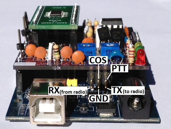
Example radio cables
Look at these pages for information about how to connect to the Kenwood TH-F6A, Yaesu FT-7900, Icom ID-800H and DB-9 - coming soonPTT
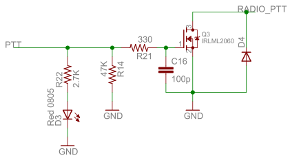
The PTT of the radio is triggered by connecting the PTT pin to ground. Some designs manage to get it to work using an NPN transistor like a 2N3904 to pull the pin low, but that can't handle much current. By using a MOSFET like the IRLML2060, much higher current can be supported. Since the MOSFET is not mounted on a heatsink is isn't able to carry the fully specified 1.2A of current for long periods of time. For PTTs that require even higher current to trigger, a relay should be connected instead.The components were selected as follows:
- - A 0.1uF capacitor is placed between the gate and ground to minimize effects of RF noise on the PTT line
- - A 47k resistor is connected to ground to lightly pull the gate down (to disable the PTT) when the PTT pin isn't being driven by the processor.
- - The zener/schottky diode (note: schematic is showing regular diode because Eagle's footprint was wrong) is connected between the PTT pin of the radio and ground to help protect the MOSFET against signals coming back from the radio.
- - A red LED is used to signal when PTT is active.
COS (Carrier Operated Squelch)
Many radios include a signal that toggles when the squelch is broken. The software can use this as part of the detection routines to tell when the receive stream is present. The most robust solutions use the markers within the bitstream itself to determine when a receive stream is present. Using the COS signal can help when the software incorrectly concludes that the stream has stopped. The image below shows the circuit to take the COS signal directly from the radio and clean it up before expsosing the signal to the IO pins of the board. A separate GPIO pin is used to drive a green LED so the software can signal when COS (either from the radio or from the bitstream) is present.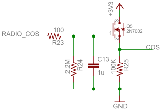
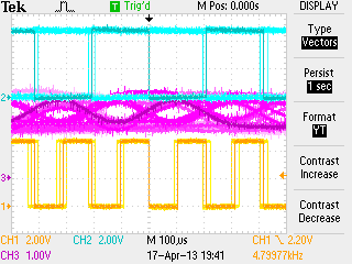
Op-amp oscillation
Special care needs to be taken to protect against the op-amp oscillating. The image below, taken with an oscilloscope, shows an example of the output signal of the transmit op-amp oscillating.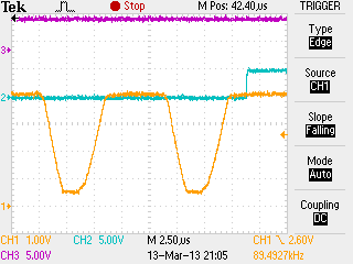
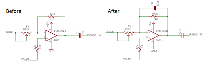
A simple fix is to place a capacitor in parallel to the feedback resistor. The image below shows the before and after circuits. The first is the one that oscillated and the second is the one that did not oscillate. For more information on how op-amps oscillate, have a look at these websites:
Why Op Amps Oscillate—an intuitive look at two frequent causes
Taming the Oscillating Op Amp
Filtering
A side effect of placing a capacitor in parallel with the feedback resistor is that the circuit becomes an integrating low pass filter. This means that the RC combination needs to be selected carefully to make sure the low pass frequency is high enough to pass all the GMSK signals and low enough so that it doesn't pass unnecessary noise.For more information on how filtering works with op-amps, have a look at these websites:
Electronics Tutorial about Op-amp Integrator Amplifier
Electronics Tutorial about Active Low Pass Filters
Ask The Applications Engineer-25 - OP AMPS DRIVING CAPACITIVE LOADS
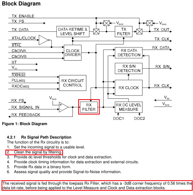
The image below, from the data sheet, shows the signal path in the CMX589 chip. The device includes its own low pass filter at 0.56 times the data rate. This gives 0.56*4800=2688Hz. This means our input filter should be higher than 2688Hz.
The image below, from electronics-tutorials.ws, shows the cutoff frequency of an op-amp low pass filter.

The filter calculations are done via this formula.
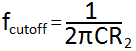
Our design needs a cutoff frequency higher than 2688Hz and it would be helpful to reuse some of the component values used elsewhere. If a value for R2 is assumed to be 100k, then a close cutoff frequency of 3386Hz can be achieved using 470pF for C.
Spice models
To better understand how well the various op-amp designs work, we ran them through a Spice simulator. After looking at the results it appears that the high frequency cutoff are too low and need to be a bit higher.To quote from the Linear Technologies website: "LTspice IV is a high performance SPICE simulator, schematic capture and waveform viewer with enhancements and models for easing the simulation of switching regulators." LTSpice IV is a free download from the Linear website: LTSpice IV
The LTSpice model files for these circuits can be found on the GMSK downloads page.
The existing input high frequency cutoff is a bit too low. The cutoff at 2.7kHz is the same as the low-pass filter already built into the CMX589. The new design has a cutoff frequency of 3.3kHz.
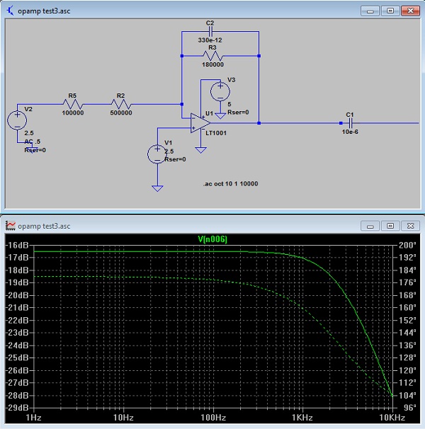
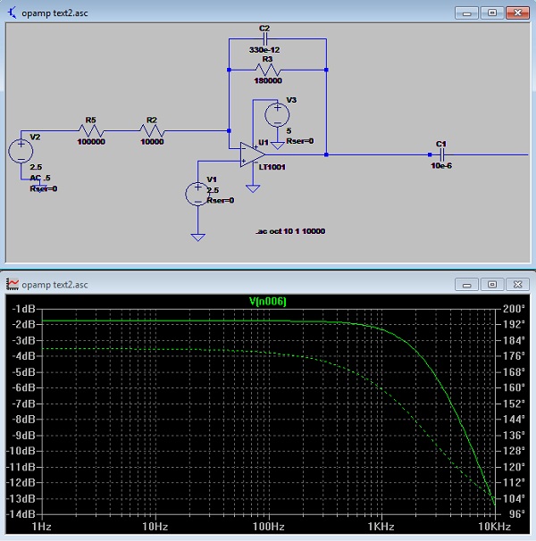
The two images below show the frequency response for the existing input design, the first one when the variable resistor is set to its highest resistance and the second one when the variable resistor is set to its lowest resistance.
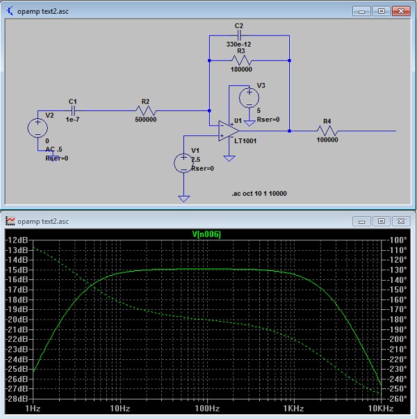
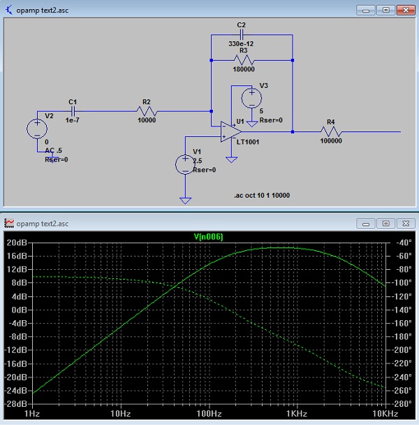
The two images below show the frequency response for the proposed input design, the first one when the variable resistor is set to its highest resistance and the second one when the variable resistor is set to its lowest resistance.
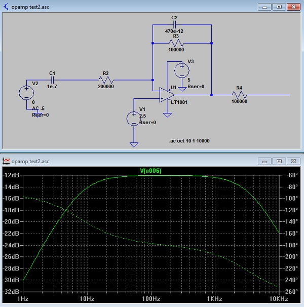
The existing high frequency cutoff is a bit too low. The cutoff at 2.7kHz. The new design has a cutoff frequency of 3.3kHz.
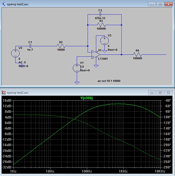
The two images below show the frequency response for the existing output design, the first one when the variable resistor is set to its highest resistance and the second one when the variable resistor is set to its lowest resistance.
The two images below show the frequency response for the proposed output design, the first one when the variable resistor is set to its highest resistance and the second one when the variable resistor is set to its lowest resistance.
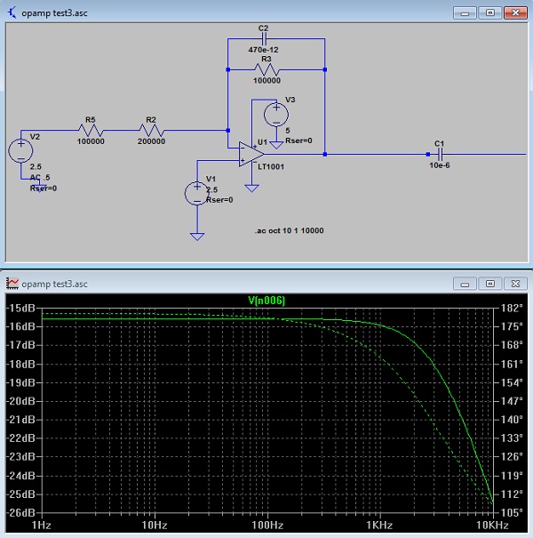
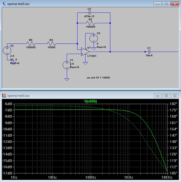
Neither is optimal, especially the low end frequency which creeps up towards 100Hz.
Op-amp gain
The image below, electronics-tutorials.ws, shows the DC gain of an op-amp.The gain calculations are done via this formula.
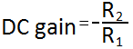
If our design uses a feedback resistor of 100k, and an input variable resistor of 200k, the gain range will range from -100k/200k=-0.5 all the way to -100k/10k=-10. The variable resistor range will vary from 200k down to about 10k.
AC coupling
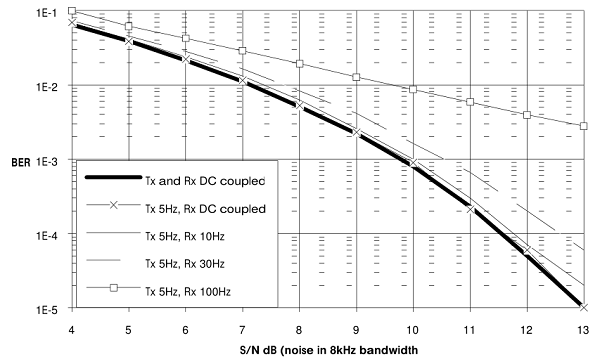
The audio signal coming from the radio needs to be AC coupled to the CMX589 device. The image below, from the data sheet, shows that the input signal should be AC coupled with a 20Hz high pass filter. It also shows that the time constant should be shorter than the time constant used on the transmit side.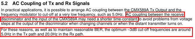
Op-amp selection
For a supply voltage of 3.3V, the less expensive op-amps cannot function well. In this case, a rail to rail opamp is needed. A good inexpensive rail-to-rail op-amp designed to operate at 1.8V and up is the MCP6002 ($0.33 at Mouser). The image below, from the 4558 data sheet shows that the device has a minimum supply voltage of 5V.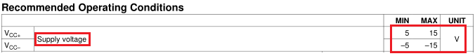
For a supply voltage of 5V, a more generic op-amp can be used. As part of the effort to keep the cost of the board to an absolute minimum, we did a series of tests with various op-amps to see which ones worked well and which were the cheapest. The images below, taken with an oscilloscope, show that the feedback signal from the CMX589 device is essentially the same regardless of which op-amp is used.
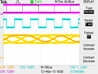 TJM4558 | 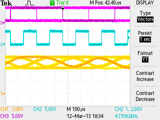 TL072CN |
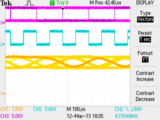 LM358N | 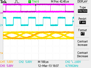 NE5532P |
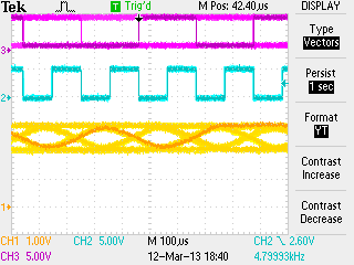 HA17458 | 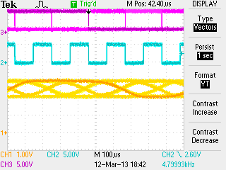 TL082CN |
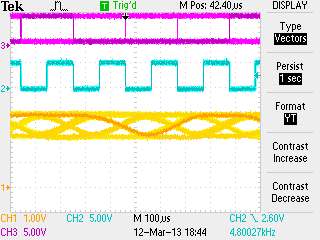 TL062CP |
Armed with the knowledge that all the op-amps performed similarly, device selection comes down to price. A survey of distributors like Mouser, Digikey, Tayda and Dipmicro showed that the DIP version of the TMJ4558 was the cheapest ($0.13 at Tayda) with an alternative of the LM358 ($0.16 at Mouser).
Adjusting the Receive and Transmit op-amp gain
The same techniques are used for adjusting the op-amp gain of both the RasPi DV and DV for Arduino adapter boards.The app-note recommends setting the signal levels from the input op-amp such that the signal measured on the feedback pin (pin 10) of the CMX589 is 1.2V peak to peak with a 5V supply. For a 3.3V supply the feedback signal should be 0.7V peak to peak. The gain for the receive op-amp is adjusted using RX variable resistor and the gain for the transmit op-amp is adjusted using TX variable resistor.
Receive levels
- Method #1 - using an oscilloscope
- - while receiving a transmission from an ICOM DStar radio, measure peak to peak voltage of the feedback signal on pin 10 of the CMX589
- - adjust the levels to 1.2V peak-to-peak for 5V supply
- - adjust the levels to 0.7V peak-to-peak for 3.3V supply
- The images below show the RX_FB signal before and after being adjusted to the optimum level.

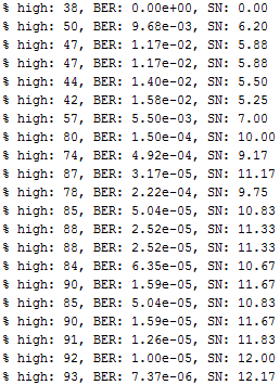
- Method #2 - using the RX_SN display software running on an Arduino
- - start the RX_SN display app
- - while receiving a transmission from an ICOM DStar radio, watch updating BER and S/N values
- - adjust the variable resistor to the point where the BER values are the lowest and the S/N values should also be the highest
- The image below shows the RX_SN software running and displaying the values as the variable resistor is adjusted to the optimum setting.
Transmit levels
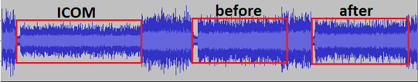
- Method #1: - measuring signal levels from an FM radio
- - using the audio output of an FM radio, measure signal levels of transmission from ICOM DStar radio using an oscilloscope or audio cable into microphone input of a PC running simple audio recording software like Audacity or PC soundcard oscilloscope software like Scope or Zelscope
- - transmit from GMSK board and measure using same FM radio
- - adjust the variable resistor so that the levels match what was measured from ICOM DStar radio
- - the screen shot below, taken from Audacity shows the signal levels from an ICOM DStar radio and the signal levels coming from the GMSK board before and after being adjusted
- Method #2: - using 2nd GMSK board and an oscilloscope
- - measure signal levels on pin 10 of GMSK for a transmission from an ICOM DStar radio
- - transmit from first GMSK board and measure again using the 2nd GMSK board
- - adjust the variable resistor such that the levels match what was measured from ICOM DStar radio
- (see the images above for the Received levels method #1
- Method #3: - listening to signal levels from an FM radio
- - listen to audio from an FM radio while transmitting from an ICOM DStar radio
- - transmit from GMSK board and listen using the same FM radio
- - adjust the variable resistor as best as you can tell by ear so that the audio levels are the same
- - can alternate back and forth between ICOM DStar radio and GMSK board
- Method #4: - using a service monitor/deviation meter
- - measure the deviation of ICOM DStar radio transmission
- - measure the deviation of GMSK board transmission
- - adjust the variable resistor such that the levels match what was measured from ICOM DStar radio
All text and images on ki6zum.com are copyright (c) 2010-2014 and may not be reproduced in any form without written permission.