Arduino shield
The design of the Arduino version of the GMSK board is very similar to the one for the Raspberry Pi. The main difference is that the Arduino runs at 5V compared to the 3.3V for the Pi.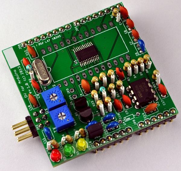
Schematic/PCB
The schematic diagram and PCB layout were done using Eagle CAD. They offer a limited free version of the software available for Windows, Mac and Linux. The Ealge files and PDF of the schematic diagram can be found on the downloads page.Firmware/software
The links to the firmware and software test files can be found on the downloads page. Note that the programming jumper needs to be removed when programming the Arduino board.Programming jumper
There is a small problem with Arduino boards that have an FTDI chip to do the USB interconnection. When the software on a PC/Mac/Linux computer opens the serial port, the drivers reset the ATMega328 chip. The Arduino bootloader takes a long time to execute. The host software typically opens the serial port and then immediately attempts to communicate with the board. This means that some amount of data sent to the Arduino is lost. The fix is to add a capacitor to slow the reset line enough to keep it from asserting low based on the length of time the reset pulse generated for that reset. An unfortunate side effect is that this breaks the Arduino programming which also relies on the reset pulse.The solution is to add a jumper (PRG) to the board to enable the capacitor when the board is in normal operation. The jumper needs to be removed when the board is being programmed.
Radio connection
The radio is connected via a 2x3 0.1" spacing male pin connector carrying the PTT, COS, GND, RX audio and TX audio signals. See the tuning instructions here.Test points
There are two test points on the board. The first one is JP3 which is the receive analog feedback signal, and the second one is JP4 which is the transmit analog signal. These two signals can be used to help adjust the variable resistors. See the tuning instructions here.Analog signal levels
The transmit and receive signals going to/from the radio respectively need to be adjusted to match the radio. See the tuning instructions here.DStar Repeater software configuration
The DStar Repeater software needs to be configured to use the DV for Arduino board. Follow the settings described on the G4KLX software config page. In the Modem configuration window within dstarrepeaterconfig, the modem type needs to be selected as "DV-RPTR V1". The Arduino will show up as a device with a name similar to /dev/ttyUSB0 and needs to be set within the configuration tool.The settings for "TX Inversion" and "RX Inversion" need to be configured to match the radio being used. This is usually done either by experimentation, or by finding the settings tested by someone else. There is a good repository of configurations stored in the gmsk_dv_node Yahoo group files section. Some radios may have different settings depending if they are being used in VHF or UHF bands.
GPIO connector pinout
The DV for Arduino board connects directly to the GPIO pins of the Arduino.| Arduino | DV for Arduino | Arduino | DV for Arduino |
|---|---|---|---|
| AREF | |||
| GND | GND | ||
| D13 | |||
| D12 | |||
| RESET | D11 | COS_LED | |
| 3V3 | D10 | ||
| 5V0 | 5V0 | D9 | PLLACQ |
| GND | GND | D8 | PTT |
| GND | |||
| VIN | D7 | COS | |
| D6 | TXDATA | ||
| A0 | D5 | RXDATA | |
| A1 | D4 | RX_SN | |
| A2 | D3 | TXCLK | |
| A3 | D2 | RXCLK | |
| A4 | TX | ||
| A5 | RX |
Voltage/current limits
The Arduino includes both 3.3V and 5V supply on the GPIO pins. The maximum current a typical Arduino can supply on the 3.3V line is about 50mA. The 5V supply can handle much more than that, the exact amount varies by they type of Arduino board and the way the power is supplied to the board. As an example, the Ethernet shield draws about 150mA, so there should be plenty of current available for the DV board.Bill of Materials
For the most part, all the parts are available from either Mouser and/or Tayda Electronics. The PCBs can come from a service such as OSH Park or Seeed Studio.The prices below are based on purchasing enough parts in bulk to make kits for at least 10 boards. Buying the parts for just a single board would cost quite a few dollars more. The pricing for the resistors and capacitors is based on buying at least multiples of 100 at a time. The pricing for parts at Tayda assumes using 15% discount they regularly post on their Facebook page.| Category | Description | Rev. 1.0 Designator | Qty | Price | Ext | Vendor link |
|---|---|---|---|---|---|---|
| Semiconductors | ||||||
| CMX589AE2 | U1 | 1 | $3.700 | $3.700 | eBay | |
| LM4558 | U3 | 1 | $0.136 | $0.136 | Tayda | |
| 2n7000 | Q1, Q2 | 1 | $0.077 | $0.154 | Tayda | |
| LEDs | ||||||
| LED Y | D1 | 1 | $0.017 | $0.017 | Tayda | |
| LED G | D2 | 1 | $0.017 | $0.017 | Tayda | |
| LED R | D3 | 1 | $0.017 | $0.017 | Tayda | |
| Crystals | ||||||
| 4.9152MHz | Y1 | 1 | $0.330 | $0.330 | Mouser | |
| Capacitors | ||||||
| 22pF (22) | C6 | 1 | $0.008 | $0.008 | Tayda | |
| 30pF (30) | C2, C3 | 2 | $0.008 | $0.008 | Tayda | |
| 470pF (471) | C1, C9, C16, C17 | 4 | $0.008 | $0.032 | Tayda | |
| 27nF (273) | C7, C8 | 2 | $0.008 | $0.016 | Tayda | |
| .1uF (104) | C4, C10, C12, C14 | 4 | $0.008 | $0.032 | Tayda | |
| 1uF (105) | C5, C11, C13, C15 | 4 | $0.088 | $0.352 | Mouser | |
| 4.7uF (475) | C18 | 1 | $0.156 | $0.156 | Mouser | |
| Resistors | ||||||
| 200k potentiometer | Rx | 1 | $0.162 | $0.162 | Tayda | |
| 500k potentiometer | Tx | 1 | $0.162 | $0.162 | Tayda | |
| 100k potentiometer | Tx | 1 | $0.162 | $0.162 | Tayda | |
| 50k potentiometer | Rx | 1 | $0.162 | $0.162 | Tayda | |
| 330 | R21, R23 | 2 | $0.008 | $0.016 | Tayda | |
| 2.7K | R22, R26, R27 | 3 | $0.008 | $0.024 | Tayda | |
| 47K | R5, R6, R8, R9, R10, R14 | 6 | $0.008 | $0.048 | Tayda | |
| 100K | R1, R3, R4, R12, R3, R25 | 6 | $0.008 | $0.048 | Tayda | |
| 1M | R2, R24 | 2 | $0.008 | $0.016 | Tayda | |
| Connectors | ||||||
| 2x3 conn | JP2 | 1 | $0.026 | $0.026 | Tayda | |
| 1x6 conn | JP9, JP10 | 2 | $0.021 | $0.042 | Tayda | |
| 1x8 conn | JP7, JP8 | 2 | $0.026 | $0.052 | Tayda | |
| 1x2 conn | PRG | 1 | $0.007 | $0.007 | Tayda | |
| 1x2 jumper | PRG | 1 | $0.017 | $0.017 | Tayda | |
| PCB | ||||||
| 2 sided PCB | 1 | $0.825 | $0.825 | Seeed Studio | ||
| 2 sided PCB - Qty 3 | 1 | $9.950 | $9.950 | OSHPark | ||
| Shipping | ||||||
| Mouser | 1 | $0.675 | $0.680 | |||
| Seeed | 1 | $0.000 | $1.000 | |||
| Tayda | 1 | $0.280 | $0.280 | |||
| Total | $8.380 |